XML shortcut is a small file, which directs svgtex plugin to the source SVG file(s). They
can be used to compose from a single *.svg file many different textures, and enrich them with
additional effects.
To follow this section, you should be at least familiar with the basics of XML syntax and conventions.
You can learn it from many sources in the Web. There is a page about it
in Wikipedia, for example. Read that text and analyze the examples, for a while. It should be enough.
Would you like to repeat the actions, shown in the text below? Download the exemplary model:
the example — a P-40B model, with textures, used in this text (the same as in the first part of svgtex description);
Let's begin with the simplest case: do you remember from
svgtex parameters details,
that the length of the path to the source file (File Name field in Plugin panel) can
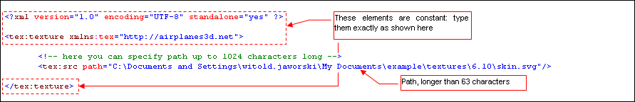
have up to 63 characters? To use longer paths, create a new *.xml file (just in the Notepad, for example).
Its content should have structure like on Fig. 1.1:
|
| Fig. 1.1 Simple XML shortcut to a SVG file (the path is longer than 63 characters) |
All elements in this XML should have the tex: namespace prefix, otherwise will be ignored.
The root node - tex:texture - is always the same. It contains just simple tex:src
reference. Type the path to the SVG file into value of its path attribute. You can use paths
up to 1023 characters, here.
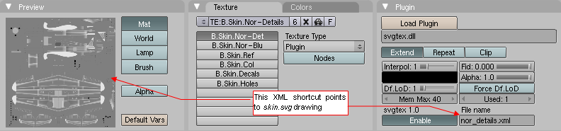
Name this file nor_details.xml. Place it in the folder, where the actual *.blend
file is located. When you type "nor_details.xml" into plugin File Name field, the
miniature of the skin.svg picture should appear in the Preview panel (Fig. 1.2).
This is the evidence that the shortcut is working properly:
|
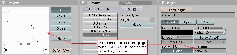
| Fig. 1.2. Usage of the nor_details.xml shortcut |
Nearly all raster textures of P-40 model, used as the example here, have been created as
a composition of some layers from skin.svg file. Many of these layers were used
more than once. For an illustration, let's have look at the B.Skin.Holes texture. It maps
small holes on the aircraft skin, and use this picture to alternate the material's opacity (alpha) value.
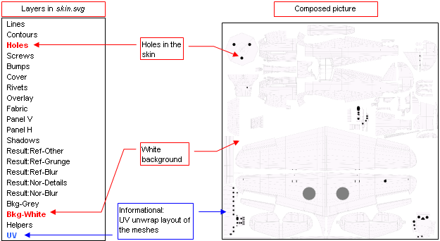
B.Skin.Holes uses holes.png raster image, which has been composed from two layers of
skin.svg: Holes and Bkg-White (Fig. 2.1). Result of this composition
has been exported from Inkscape to the raster file:
|
| Fig. 2.1 Composition of the airplane skin holes: layers Holes + Bkg-White |
To make the Fig. 2.1 clearer, I also have turned on the visibility of the UV layer.
It contains the UV unwraps of the Blender meshes. The size and location of the holes is obvious,
when you can see these meshes below.
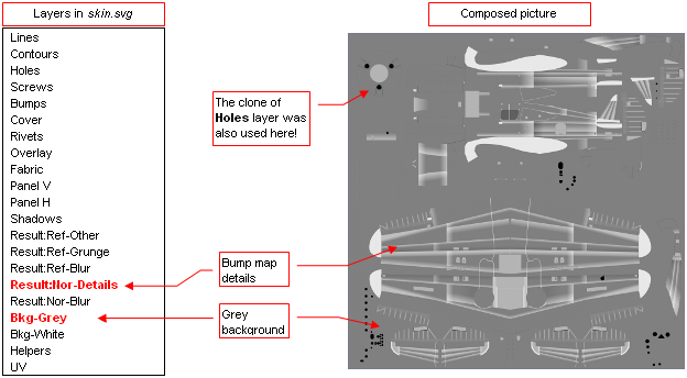
From the same skin.svg file comes the picture for the bump map texture - nor_details.png file.
It is composition of many layers, and each of them has different opacity setting. To simplify the
export to the raster image, I have decided to place clones of these layers to a single layer:
Result:Nor-Details. Then the resulting raster image - nor_details.png - is exported
as composition of Result:Nor-Details and Bkg-Grey layer(Fig. 2.2):
|
| Fig. 2.2 Composition of the bump map: Result:Nor-Details + Bkg-Grey |
The skin.svg file, with layer visibility set as on Fig.
2.2, we have used in the previous example (compare the texture preview on Fig.
1.2).
XML shortcuts allow to use source *.svg drawing as something like "image library".
The same skin.svg file, used in the previous example as the bump map
(in B.Skin.Nor-Details texture — see Fig. 1.2), we will use here again.
We use it as the source for the holes texture (B.Skin.Holes), without applying any
changes to the source SVG picture. Fig. 2.3 shows the content of holes.xml shortcut,
which creates this effect:
|
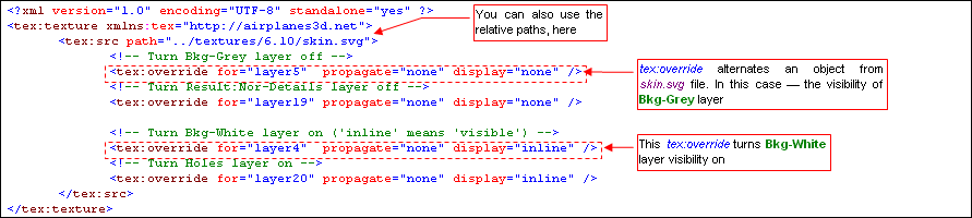
| Fig. 2.3 XML shortcut, alternating layers visibility in the source SVG file. |
Comparing to the previous example (Fig. 1.1), the tex:src node
contains here some new tex:override elements. The role of tex:src is to
point the parser the source SVG file to load. The role of each tex:override is
to alternate some properties of particular element from the source SVG file. The id of the "target"
for this alternation is specified in for attribute value. On the example from Fig. 2.3,
first two tex:override elements turn off visibility (display=”none”) of Bkg-Grey and Ref:Nor-Details layers.
The next two tex:overrides are used to turn on visibility (display=”inline”)
of of Bkg-White and Holes layers. Propagation of these changes to the target element's children nodes
is controlled by the propagate attribute. In this example, propagation is turned off - their visibility
does not matter, when their "parent" becomes invisible.
Fig. 2.4 shows the result of holes.xml shortcut:
|
| Fig. 2.4. Content of skin.svg, „filtered” by the holes.xml shortcut |
Notice, that in the example above I have typed id of layer Bkg-Grey as „layer5”,
„layer19” for Result:Nor-Details layer, and so on. How do I know that they have such ids?
You have to find them in the source SVG file (Fig. 2.5):
|
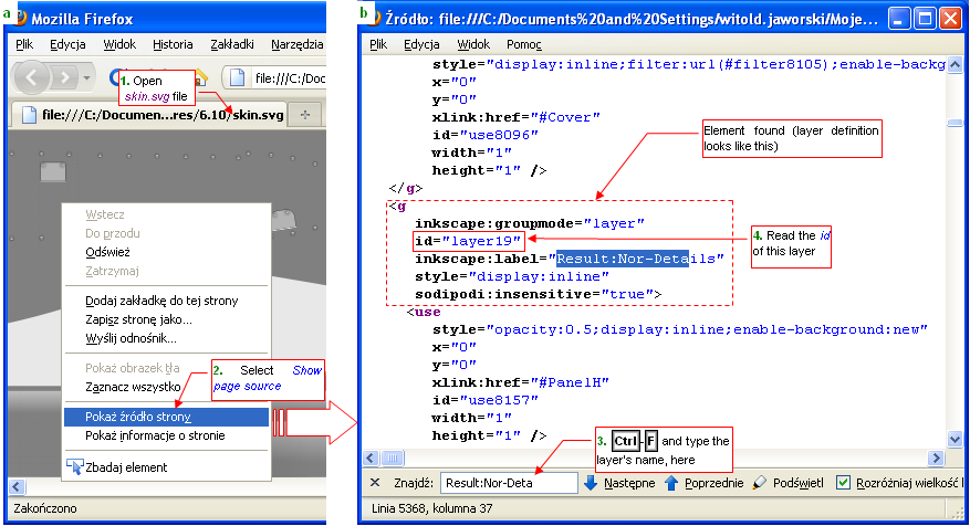
| Fig. 2.5 Discovering in SVG source the id value of the layer, found by the name |
Open the SVG file in a web browser (Firefox, for example). Open the context menu and select
the View page source command. In the source editor window press Ctrl-F (Find),
and find the layer definition, using its name (Fig. 2.5b). The id attribute is
the unique identifier of this element, referenced by tex:override.
tex:texture element is always the root of XML shortcut document (Fig. 1.1).
Except tex: namespace declaration (xmlns attribute) it has not any attributes.
tex:texture contains one (or more) tex:src elements. You can also place any other
SVG element there (without any namespace prefix).
tex:src element tells the interpreter to load a source SVG file. Its full name is placed in the
path attribute, and can have up to 1023 characters. tex:src can contain zero
or more tex:override elements.
tex:override element alternates the properties (attribute values) of an element in the SVG source file (pointed
by the parent tex:src). The identifier (id) of this "target" node has to be specified
in the mandatory for attribute. Additionally, tex:override should contain some SVG attributes,
alternating the corresponding values of the "target" element (display, for example). The mandatory
propagate attribute specifies the alternation scope. When propagate=”all”, it
alternates the target element and all its descendants. When propagate=”none”, the children of the target
remain unaltered.
In general, you can place in a tex:override node all style attributes, described in the
SVG 1.1 specification.
I have listed below the names of the most typical SVG properties to be overridden:
- display: visibility of the element (visible when display=”inline”, invisible when display=”none”);
- opacity: general element opacity — a number from 0.0 to 1.0 range. For example: opacity=”0.5” means 50% of transparency;
- fill: fill color (for example fill=”#080808” fill contours with grey color, that contains 50% of the black);
- fill-opacity: opacity, that has no influence on the stroke — a number from 0.0 to 1.0. For example fill-opacity=”0.6”
means that the contour interior has 40% of transparency;
- stroke: color of the borderline (for example stroke=”#080000” gives dark red border);
- stroke-opacity: opacity of the border — a number from 0.0 to 1.0 range;
- stroke-width: the width of the borderline — any positive number;
- stroke-dasharray: a reference to a dash pattern (details — see the SVG specification);
- font: a reference to a font definition (used in text element) (details — see the SVG specification);
- font-size: an positive number, with optional unit (details — see the SVG specification);
- filter: a reference to filter definition (details — see the SVG specification);
- mask: a reference to mask definition (details — see the SVG specification);
- clip-path: a reference to path element that "clips" the drawing (details — see the SVG specification);
Fig. 3.1 is another example of XML shortcut. It presents some of the rules, described above.
(Names of the SVG source files: t.svg i w.svg do not refer to any existing entities.
This is just the example of some syntax structures, only.):
|
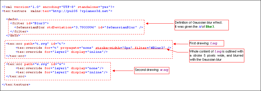
| Fig. 3.1 Example of an advanced XML shortcut |
This shortcut composes pictures from two drawings: t.svg and w.svg. (This is
a case of multiple tex:src elements). In addition, there is a filter definition (inside the
defs group. It is a Gaussian blur effect, having identifier (id) = "Blur3". This effect
is used to blur content of the t.svg picture. Id is done by the first tex:override
element (with attribute filter=”#Blur3”). Notice, that this tex:override has in
for attribute the id of its own parent element (the tex:src node with t="t").
It is also allowed.
Well, if you have reached this paragraph, dear Reader, it means that you are a programmer
or - at least - have the programmer's inclinations. Would you like to write in Python a nice
GUI gadget that will enable ordinary users to create XML shortcuts? The xml parser is among Python
standard packages, there are also some windowing environments around... Personally I do not need it,
so I have not written such thing, yet!